
One of the most common questions from transformer manufacturers, EPC contractors and purchasing engineers is:
How many radiator panels does a transformer need?
The answer cannot be determined from transformer MVA alone.
A 10 MVA transformer and another 10 MVA transformer can require different numbers of radiator panels because their:
may be different.
For this reason, professional transformer radiator sizing starts with the heat that must be dissipated, rather than simply matching a certain number of panels to a particular MVA rating.
For liquid-immersed transformers, removable radiators are covered by IEC 60076-22-2, which specifies mechanical and operational requirements, preferred dimensions and testing requirements. The standard’s cooling-performance method also makes clear that radiator heat dissipation depends on factors including radiator height, average oil temperature rise and correction coefficients.
This guide explains how engineers determine the required number of radiator panels and what information should be provided when requesting a transformer radiator quotation.
If someone asks:
“How many radiator panels does a 20 MVA transformer need?”
there is no technically valid answer without additional information.
The correct engineering sequence is:
Transformer losses
↓
Required heat dissipation
↓
Cooling mode
↓
Radiator heat dissipation per panel
↓
Required radiator surface area
↓
Number of radiator panels
A simplified calculation is:
where:
In real transformer engineering, the calculation is more complicated because the performance of a radiator depends on its geometry and operating conditions.
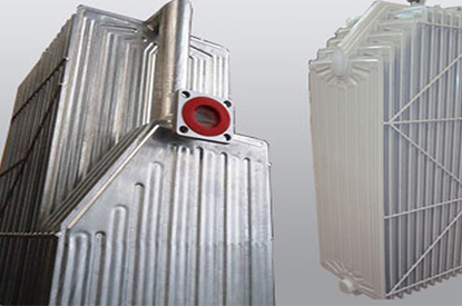
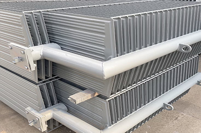
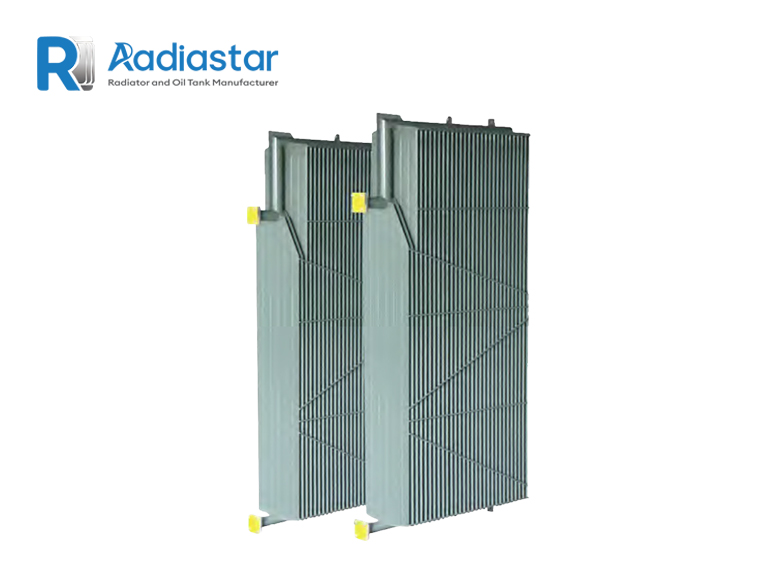
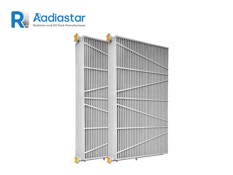
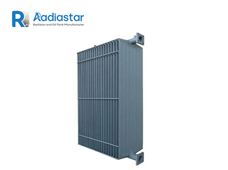
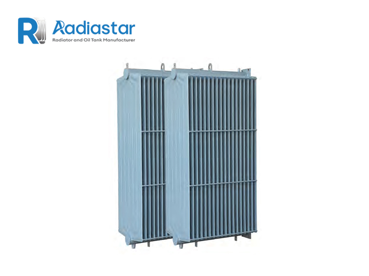
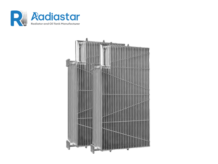
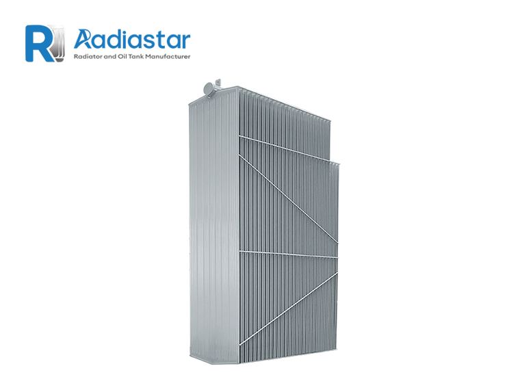
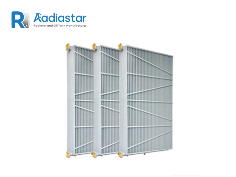
A transformer radiator is normally constructed from multiple pressed or formed steel cooling elements connected to upper and lower header pipes.
The complete assembly may be called a:
Terminology varies between manufacturers and regions.
This distinction is important when purchasing.
For example, one supplier may describe a complete radiator assembly as one radiator, while another may describe each individual cooling element as a panel.
Therefore, a technical quotation should specify the actual:
This avoids comparing different suppliers based only on the word “panel.”
The required number of radiator panels is influenced by several parameters.
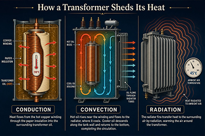
The cooling system must remove the heat generated by transformer losses.
These include:
A transformer with higher total losses requires more cooling capacity even if two transformers have the same MVA rating.
The cooling designation has a major effect.
Typical methods include:
For ONAN, oil circulation and air circulation are natural.
For ONAF, oil circulation remains natural while air is forced through the radiator using fans.
IEC 60076-22-2 states that the radiator cooling-performance diagrams are applicable to ONAN and that ONAF, OFAN and OFAF applications require configuration-specific multiplicative adjustments.
Therefore:
The same physical radiator may have different cooling capacities under ONAN and ONAF conditions.
MVA is useful for understanding the approximate scale of the transformer, but it does not directly equal heat generation.
Consider two transformers:
20 MVA
20 MVA
They may have different:
Consequently, the required radiator capacity can differ.
This is why a professional radiator manufacturer should request transformer loss data before finalizing radiator quantity.
The first engineering step is to determine the heat that the cooling system needs to remove.
A simplified relationship is:
where:
For a simplified calculation:
where:
For a real transformer design, the complete loss model should be used rather than relying on a simplified equation.
The radiator manufacturer should therefore obtain the relevant loss data from the transformer manufacturer.
Next, determine whether the transformer is designed for:
Oil Natural Air Natural
or:
Oil Natural Air Forced
or another cooling arrangement.
This is essential because the radiator’s heat-transfer performance changes with airflow.
For ONAN, natural convection determines the external air-side heat transfer.
For ONAF, fans increase air movement and therefore increase heat-transfer performance.
A research study on ONAN radiator configurations found that changing radiator geometry can materially affect cooling performance; for the configuration investigated, increasing fins from 18 to 30 increased calculated cooling capacity by about 50%, while increasing radiator length from 2,000 to 3,000 mm increased it by about 40%. These figures are study-specific, not universal design factors, but they demonstrate why panel geometry matters.
A professional radiator calculation does not simply say:
One panel = X kW.
The actual heat dissipation depends on the radiator design and operating condition.
IEC 60076-22-2’s cooling-performance methodology relates specific heat dissipation to parameters including:
The standard identifies correction coefficients such as KN, KP and KDH for the radiator configuration and installation conditions.
This means a 2,000 mm-high radiator and a 3,000 mm-high radiator should not be treated as having identical heat-dissipation performance per element.
For preliminary engineering, the concept can be represented as:
where:
The actual calculation method should follow the applicable standard, manufacturer’s tested performance data and the transformer thermal design.
This formula is useful because it demonstrates an important point:
Panel quantity is the result of thermal design—not an independent specification.
Radiator height is one of the key design parameters.
A taller radiator generally provides more effective heat-transfer area.
IEC 60076-22-2’s cooling-performance approach explicitly relates radiator performance to element height and average oil temperature rise.
For example, consider two hypothetical radiator designs:
Radiator A:
Height = 1,500 mm
Radiator B:
Height = 3,000 mm
Even if both use the same general pressed-panel construction, their cooling capacity will not be identical.
Therefore, saying:
“The transformer needs 20 panels”
is incomplete unless the panel dimensions are also defined.
A complete radiator assembly can contain multiple cooling elements.
For example:
Radiator assembly
→ Header
→ Element 1
→ Element 2
→ Element 3
→ …
→ Element 20
The number of elements affects:
IEC 60076-22-2 includes a correction coefficient associated with the number of radiator elements, which reflects the fact that radiator performance does not increase indefinitely in a perfectly linear manner simply by adding elements.
This is one of the reasons engineers should use manufacturer performance data rather than a simple area-only calculation.
Radiator geometry also includes:
These parameters influence both the cooling surface and airflow.
If panels are installed too closely together, natural airflow can be restricted.
If spacing is increased excessively, the overall radiator bank may become unnecessarily large.
A good design balances:
Heat-transfer area
with
Airflow
and
Installation space.
For ONAN cooling, the radiator relies on natural convection.
The design therefore needs to consider:
IEC 60076-22-2 specifies a type-test approach for determining radiator cooling performance under ONAN conditions. The resulting performance information can then be used in radiator calculations.
A simplified engineering process is:
The final number should then be checked against:
For ONAF, fans increase airflow through the radiator bank.
The calculation becomes:
The exact relationship is configuration-dependent.
This is important because there is no universal rule such as:
“Adding fans doubles the radiator capacity.”
Fan performance depends on:
IEC 60076-22-2 specifically notes that ONAN cooling-performance diagrams require configuration-specific adjustment for ONAF applications.
Consider a hypothetical transformer with:
A preliminary calculation would be:
Therefore:
20 radiator assemblies
would be required based on the assumed performance value.
However, this is only an illustrative calculation.
The actual number must be verified using:
This distinction is important for technically credible SEO content.
You will sometimes see tables such as:
| Transformer Rating | Typical Radiator Quantity |
|---|---|
| 5 MVA | X |
| 10 MVA | X |
| 20 MVA | X |
| 30 MVA | X |
| 50 MVA | X |
These tables may be useful as rough commercial references, but they should not be treated as engineering design rules.
Why?
Because the number of panels changes with:
A technically responsible supplier should avoid promising an exact panel quantity based only on MVA.
Suppose a radiator is designed for:
Ambient temperature = 25°C
and another project specifies:
Ambient temperature = 40°C
The second project has less temperature difference available between the oil and surrounding air.
Therefore, the radiator may require:
This is especially important for transformers installed in:
High ambient temperature should always be included in the radiator specification.
Radiator sizing is directly related to allowable temperature rise.
The basic concept is:
A higher allowable temperature difference generally provides a greater driving force for heat transfer.
But transformer thermal design cannot simply increase temperature rise without considering:
Therefore, radiator quantity must be coordinated with the transformer’s complete thermal design.
For ONAN systems, natural oil circulation is particularly important.
Hot oil rises through the transformer tank and enters the upper radiator header.
The oil cools inside the radiator and returns through the lower connection.
This creates the thermosiphon effect.
The radiator therefore needs suitable:
A radiator with a large surface area does not automatically guarantee good cooling if the oil circulation is poorly designed.
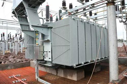
The physical arrangement of the transformer can limit radiator installation.
Engineers need to consider:
For example, the thermal calculation may indicate that 24 elements are required, but the available tank side may only accommodate a certain number per radiator assembly.
The solution may therefore be:
More radiator assemblies
rather than simply making one radiator assembly wider.
This is why thermal design and mechanical design must be completed together.
This distinction is extremely important in purchasing.
Imagine a transformer has:
4 radiator assemblies
and each assembly contains:
6 cooling elements
The specification may be described as:
4 radiators × 6 elements
or:
24 radiator elements
These are not necessarily equivalent terms.
When requesting a quotation, always ask the supplier to state:
This prevents significant confusion in international procurement.
A common radiator arrangement may look like:
Transformer tank
→ Upper valve
→ Upper header
→ Cooling elements
→ Lower header
→ Lower valve
Multiple radiator assemblies are installed around the transformer tank.
Each assembly can be isolated using radiator valves.
This makes maintenance easier.
Some transformer specifications explicitly require individually removable radiators and valves so that an individual radiator can be removed without draining the complete transformer.
For a professional transformer radiator system, valves are not merely accessories.
They can allow:
For replacement projects, the valve and flange dimensions must match the transformer tank.
This is another reason that radiator quantity cannot be considered independently from the mechanical connection design.
No.
Adding more radiator elements generally increases available cooling area, but the relationship is not unlimited.
At some point, additional elements may provide diminishing practical benefits because of:
Research on ONAN radiator configurations demonstrates that cooling performance changes with both fin count and radiator length, showing that radiator geometry must be considered as a complete system rather than simply counting elements.
The objective is not:
Maximum number of panels
The objective is:
Required cooling capacity with an efficient, manufacturable and maintainable radiator configuration.
There is no universal answer.
A preliminary estimate requires at least:
For a quotation, the best approach is to provide the transformer technical specification or drawing.
The supplier can then calculate the required radiator configuration.
Any online table giving one fixed number for every 10 MVA transformer should therefore be treated as a rough reference, not an engineering calculation.
Again, MVA alone is insufficient.
Two 20 MVA transformers may have substantially different radiator requirements.
For example:
Transformer A
Transformer B
Transformer B may require more radiator surface even though both transformers have the same MVA rating.
At 50 MVA and above, radiator design becomes increasingly dependent on the complete transformer cooling system.
The engineer may need to evaluate:
A recent engineering review notes that removable radiators are widely used in high-capacity liquid-immersed transformer cooling systems and highlights radiator height, element configuration and cooling method as important design considerations.
For larger transformers, it is particularly important to distinguish between:
radiator element quantity
and
radiator bank quantity.
An ONAN/ONAF transformer may have a single radiator bank capable of operating in both modes.
For example:
ONAN:
Natural air cooling
ONAF:
Fans switched on
The same radiator geometry may therefore have:
The designer must verify both.
If the transformer has an ONAN/ONAF nameplate rating, the radiator system must support the specified cooling conditions.
For ONAF systems, don’t confuse:
Number of radiator panels
with:
Number of fans.
For example:
6 radiator assemblies + 4 fans
is a different specification from:
4 radiator assemblies + 6 fans.
Fan performance depends on airflow distribution and radiator geometry.
The fans should therefore be selected together with the radiator bank.
The most common radiator materials include carbon steel, while stainless steel may be specified for particular environments.
Material selection affects:
IEC 60076-22-2 also addresses requirements related to materials and coatings for removable radiators.
For standard outdoor applications, properly protected carbon steel is widely used.
For aggressive environments, the project may specify stainless steel or a more demanding corrosion-protection system.
Material thickness is another important parameter.
A thinner panel can reduce weight and material consumption, but mechanical integrity and pressure resistance must be maintained.
A recent technical review of transformer cooling design reports IEC 60076-22-2 radiator steel thickness requirements and notes that greater thickness can be selected for mechanical considerations.
The final thickness should therefore be determined according to:
It should not be selected solely according to radiator price.
The radiator is part of the transformer’s oil-containing system.
A radiator with insufficient weld quality or poor sealing can result in oil leakage.
Therefore, quality inspection should normally include appropriate:
IEC 60076-22-2 defines type and routine test requirements for removable radiators.
For purchasing engineers, asking for the manufacturer’s inspection and test plan is a useful way to distinguish a professional radiator supplier from a general steel fabrication company.
If you want an accurate answer to:
How many radiator panels does my transformer need?
send the supplier the following information.
A transformer GA drawing is even better.
A radiator manufacturer can use the following workflow.
Determine no-load and load losses.
ONAN, ONAF or other.
Calculate the thermal load under each cooling condition.
Determine:
Use tested or validated radiator performance data.
Account for configuration and installation conditions.
Determine the number of assemblies/elements.
Verify valves, flanges, tank connections and available space.
Confirm temperature-rise requirements.
Only after the thermal and mechanical calculations are confirmed.
Wrong:
30 MVA = 20 panels.
There is no universal relationship.
Two transformers with identical MVA may generate different heat.
A radiator designed for 25°C may not provide the same performance at 40°C or 45°C.
Radiator height and geometry significantly affect cooling performance.
Fan-assisted cooling changes the radiator’s heat-transfer conditions.
Always define exactly what “panel” means.
A low-cost radiator that cannot achieve the required cooling capacity is not economical.
Radiastar supplies transformer radiators for liquid-immersed transformer applications, with configurations designed according to the customer’s transformer thermal and mechanical requirements.
Radiator configurations can be developed according to:
For replacement projects, the existing radiator drawing or dimensional data can be used to reproduce the required configuration.
For new transformer projects, transformer loss data and cooling requirements allow the radiator quantity and configuration to be calculated from the actual thermal requirements.
The professional answer is:
The number of radiator panels cannot be determined from transformer MVA alone.
The required quantity depends primarily on:
Transformer losses
Cooling method
Radiator dimensions
Temperature rise
Ambient temperature
Radiator heat-dissipation performance
Installation configuration
A simplified calculation is:
but the value of Qper panel must come from appropriate radiator performance data under the specified operating conditions.
For ONAN radiators, IEC 60076-22-2 relates cooling performance to radiator height, average oil temperature rise and correction coefficients. For ONAF and other forced-air configurations, configuration-specific adjustments are required.
Therefore, an experienced transformer radiator manufacturer should not quote a final panel quantity based only on:
“My transformer is 20 MVA.”
Instead, the supplier should evaluate the complete transformer cooling specification.
Before placing an order, confirm:
| Parameter | Required |
|---|---|
| Transformer rating | kVA / MVA |
| Transformer losses | kW |
| Cooling mode | ONAN / ONAF |
| Ambient temperature | °C |
| Oil temperature rise | °C / K |
| Radiator height | mm |
| Center distance | mm |
| Element width | mm |
| Element quantity | pcs |
| Fin pitch | mm |
| Header diameter | mm |
| Flange size | mm |
| Material | Carbon steel / Stainless steel |
| Surface treatment | Required |
| Fan system | If ONAF |
| Installation | Indoor / Outdoor |
| Quantity | Complete assemblies |
Determining how many radiator panels a transformer needs is a thermal-design problem, not simply a purchasing rule.
The correct approach is:
Transformer losses → Required heat dissipation → Cooling method → Radiator performance → Panel configuration → Number of radiator assemblies → Thermal verification
For standard ONAN transformers, natural oil and air circulation make radiator surface area, height and geometry particularly important.
For ONAF transformers, fans increase the air-side heat transfer, but fan airflow and radiator configuration must be evaluated together.
The most reliable way to obtain the correct radiator quantity is to provide the radiator manufacturer with the transformer rating, losses, cooling designation, ambient temperature, temperature-rise requirements and transformer/radiator drawing.
That information allows the supplier to determine not only how many radiator panels are required, but also what size, configuration and cooling capacity each radiator should have.
For international procurement, this is far more reliable than selecting a radiator based on a generic MVA-to-panel table.