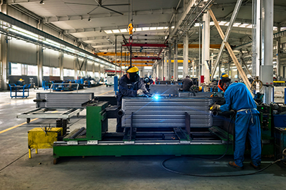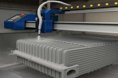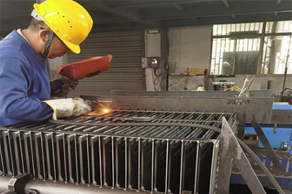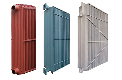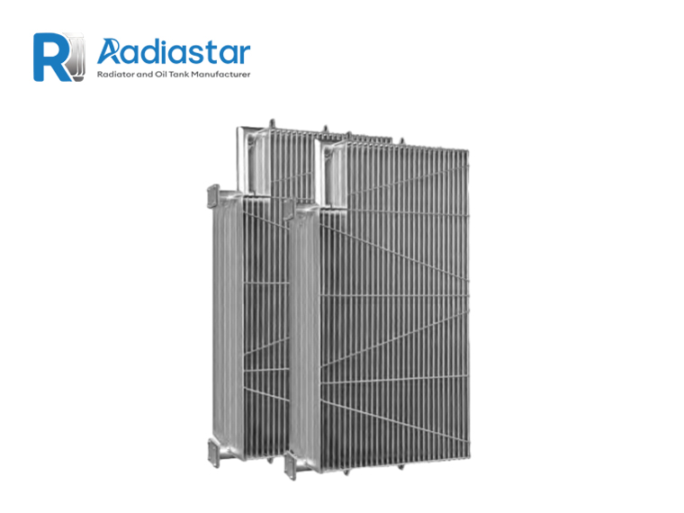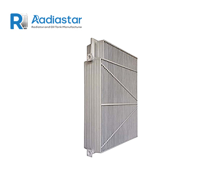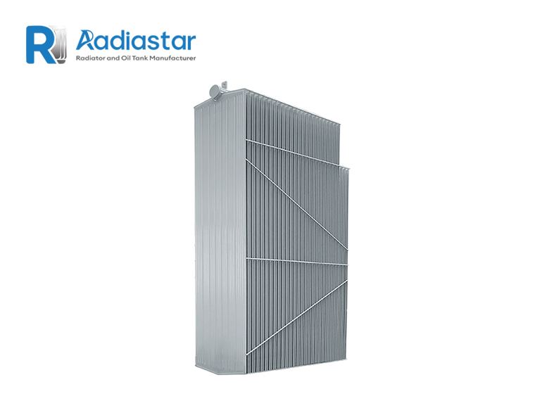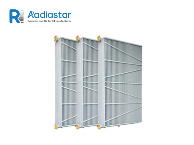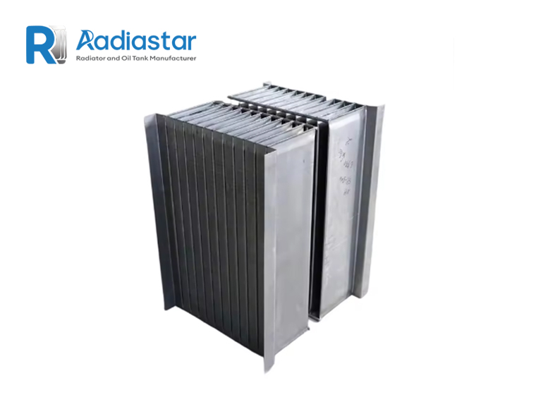

Selecting the correct transformer radiator is not simply a matter of choosing a radiator with a larger surface area. For an oil-immersed transformer, the radiator is part of the thermal management system, and its performance must be matched to the transformer’s losses, cooling method, allowable temperature rise, oil circulation, ambient conditions, and mechanical arrangement.
A properly selected radiator must remove sufficient heat under the specified operating conditions without creating excessive oil-flow resistance or compromising the transformer’s thermal performance.
For this reason, engineers normally approach transformer radiator sizing through a sequence of calculations:
Transformer rating → Transformer losses → Required heat dissipation → Cooling method → Radiator thermal capacity → Number of radiator panels → Radiator dimensions and arrangement
The transformer MVA rating is an important starting point, but MVA alone does not determine the required radiator size.
IEC 60076-2 establishes requirements related to temperature rise for liquid-immersed transformers and defines cooling methods and temperature-rise test procedures.
For removable transformer radiators, IEC 60076-22-2 specifically addresses radiators used with liquid-immersed transformers, including service conditions, mechanical requirements, preferred dimensions, and type and routine tests.
This guide explains how engineers can approach transformer radiator selection from a practical design perspective.
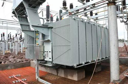
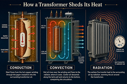
A transformer radiator transfers heat from the insulating liquid to the surrounding air.
During operation, electrical losses inside the transformer are converted into heat. The heat raises the temperature of the transformer oil and active parts. The heated oil moves toward the upper part of the tank, while cooler oil returns from the radiator toward the lower part of the transformer.
In a conventional oil-immersed transformer with natural cooling, this circulation can occur through natural convection.
A simplified thermal path is:
Transformer losses → Oil heating → Oil circulation → Radiator → Heat transfer to air
The radiator therefore has two important functions:
A radiator with a large surface area is not automatically a good radiator. Hydraulic resistance, oil-flow distribution, fin geometry, connection arrangement and installation conditions also affect actual performance.
The first parameter normally provided by a transformer purchaser is the rated power:
However:
Transformer MVA is not the same as transformer heat load.
Two transformers with the same rated power can have different losses because of differences in:
Therefore, the transformer radiator should preferably be selected using the actual transformer loss data supplied by the transformer manufacturer.
The total heat that must ultimately be dissipated by the cooling system is closely related to transformer losses.
For a typical liquid-immersed transformer, the main losses include:
No-load loss is primarily associated with the transformer core and exists whenever the transformer is energized.
It is commonly designated as:
P₀
Load loss is primarily related to winding current and other load-dependent losses.
It is commonly designated as:
Pₖ
Load loss changes approximately with the square of the load current.
If the transformer operates at a fraction x of rated load, a simplified relationship is:
Pload ≈ x² × Pk
Therefore, a simplified total-loss calculation can be expressed as:
Ptotal ≈ P₀ + x²Pk
where:
For example, if a transformer has:
then:
Ptotal ≈ 10 + (0.8² × 80)
Ptotal ≈ 61.2 kW
This does not mean that 61.2 kW is automatically the final radiator design value. The engineer must still consider the specified temperature-rise condition, cooling mode, ambient temperature and transformer thermal design.
This distinction is important when discussing transformer radiator calculation.
Once transformer losses are known, the next step is determining how much heat the cooling system must remove.
The cooling system may consist of:
For a conventional radiator-cooled transformer:
Required radiator heat dissipation ≈ heat that must be transferred from the transformer oil to ambient air
The exact thermal balance depends on the transformer design.
The designer therefore should not simply take the transformer MVA and multiply it by a generic “radiator factor.”
Instead, the calculation should use the transformer manufacturer’s thermal design data.
IEC 60076-2 specifically addresses temperature-rise limits and temperature-rise testing for liquid-immersed transformers, making temperature rise a fundamental part of the cooling-system design.
Cooling method is one of the most important factors in radiator selection.
Common cooling arrangements include:
Oil Natural Air Natural
Oil circulates naturally through the transformer and radiator, while heat is dissipated to surrounding air through natural convection.
This is widely used for distribution and power transformers where the required cooling capacity can be achieved without forced airflow.
Oil Natural Air Forced
Oil circulation remains natural, while fans force air across the radiator surface.
Compared with ONAN operation, forced airflow can increase the radiator’s heat-transfer capability.
Oil Forced Air Forced
Oil is circulated using pumps and air is forced across radiators or air coolers.
This arrangement is used when higher cooling capacity is required or where transformer thermal design requires controlled forced circulation.
Oil Forced Water Forced
Heat is transferred through an oil-to-water heat exchanger.
This is generally used for larger or specialized transformer installations where the site cooling arrangement supports a water-based system.
IEC 60076-22-3 covers liquid-to-air heat exchangers used in cooling circuits of liquid-immersed transformers, while IEC 60076-22-6 addresses electric fans used with transformer cooling systems and radiator blowing applications.
The same physical radiator can have different thermal performance depending on how it is operated.
For ONAN, heat transfer depends heavily on:
For ONAF, fans increase air movement across the radiator surface.
Therefore, the same radiator bank may be designed for different operating stages.
A transformer might have a rating such as:
ONAN / ONAF
This means the transformer can operate at one power level under natural cooling and a higher power level when forced-air cooling is activated.
When selecting the radiator, engineers should therefore ask:
The radiator manufacturer should receive these requirements before finalizing the design.
After determining the required thermal capacity, the next question is:
How many radiator panels are required?
The basic engineering relationship is:
Number of radiator panels = Required heat dissipation ÷ Heat dissipation per panel
However, this calculation is only valid when the heat-dissipation performance of one panel is known under the same test or operating conditions.
This is important because radiator capacity depends on:
Therefore, it is not technically correct to say that every radiator panel of a certain size has one universal kW rating.
Assume the transformer cooling design requires:
120 kW
and the selected radiator configuration has a verified thermal capacity of:
20 kW per radiator bank
Then:
120 ÷ 20 = 6 radiator banks
The final design may require additional engineering margin or a different arrangement depending on the transformer specification.
The 20 kW value in this example is illustrative only. Actual radiator capacity must come from the manufacturer’s validated thermal data or the transformer thermal design.
Once the required number of radiator panels is known, the engineer needs to determine the physical dimensions.
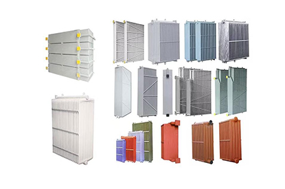
Important dimensions include:
The distance between the upper and lower oil connection centers is one of the most important radiator dimensions.
Typical projects may require different center distances depending on transformer tank dimensions and piping arrangements.
For example:
500 mm
1000 mm
1500 mm
2000 mm
2500 mm
3000 mm
and larger custom configurations.
The actual dimension should be selected according to the transformer tank layout and thermal requirement.
Fin width influences the available heat-transfer surface.
Common designs may use different widths depending on:
Fin thickness affects:
A thicker fin is not automatically better. The optimum thickness depends on the radiator design, material and manufacturing requirements.
The number of fins directly influences the available heat-transfer surface.
More fins can increase the surface area within a given radiator envelope, but increasing fin density can also influence:
Therefore, fin count should be selected as part of the complete radiator design rather than independently.
A practical transformer radiator sizing process can be summarized as follows.
Obtain:
Rated power: MVA
For example:
20 MVA
Request:
Do not estimate these values from MVA when actual manufacturer data are available.
Determine:
Determine whether the transformer uses:
ONAN
ONAN/ONAF
OFAF
or another cooling arrangement.
Use the transformer thermal design and specified temperature-rise requirements.
Possible options include:
The mechanical interface must also match the transformer tank.
Define:
Calculate the required number of radiator sections or banks based on verified thermal performance.
Confirm that the radiator configuration provides acceptable oil-flow resistance and supports the required natural or forced circulation.
The final radiator arrangement should be verified as part of the complete transformer cooling system.
This is the step that separates a proper engineering design from a simple radiator-area estimate.
When requesting a quotation, sending only:
“20 MVA transformer radiator”
is usually insufficient.
A professional RFQ should include as many of the following parameters as possible.
| Parameter | Example |
|---|---|
| Transformer rating | 20 MVA |
| Rated voltage | 110/11 kV |
| Cooling method | ONAN/ONAF |
| No-load loss | 12 kW |
| Load loss | 95 kW |
| Temperature rise | As specified |
| Ambient temperature | 40°C |
| Altitude | 1000 m |
| Radiator type | Detachable finned radiator |
| Center distance | 1500 mm |
| Fin width | Project-specific |
| Fin thickness | Project-specific |
| Number of fins | Project-specific |
| Radiator quantity | To be calculated |
| Connection | DN / flange specification |
| Material | Carbon steel / stainless steel |
| Surface treatment | Painting / galvanized |
| Installation | Outdoor |
| Standard | IEC / project specification |
This information allows the radiator supplier to make a technically meaningful proposal rather than simply quoting a standard radiator.
Carbon steel is widely used for transformer radiators because it offers a balance of:
For outdoor applications, surface protection is important.
Possible treatments include:
Stainless steel may be selected where the operating environment requires increased corrosion resistance.
The appropriate material should be determined by:
A radiator for a coastal installation should not necessarily use the same corrosion-protection system as one installed in a dry inland environment.
Thermal performance is only one part of radiator quality.
Because transformer radiators contain insulating liquid, leakage prevention is critical.
A radiator manufacturer should have appropriate procedures for checking:
IEC 60076-22-2 includes requirements and testing considerations applicable to removable radiators used on liquid-immersed transformers.
The exact pressure and test duration should be specified according to the applicable standard, project specification and manufacturer’s qualified procedure rather than using an arbitrary value.
A 20 MVA transformer does not automatically require a specific radiator size.
The actual losses and thermal requirements are essential.
Heat-transfer performance depends on operating conditions.
A single W/m² value without stating:
can produce an unreliable calculation.
A radiator system designed for ONAN may require fans to achieve the required ONAF capacity.
The two operating conditions should be considered separately.
The radiator must physically connect to the transformer tank.
Engineers should verify:
More radiator sections do not automatically mean proportionally better cooling.
The complete oil circulation path must be considered.
Before approving a radiator design, check the following:
For a custom transformer radiator, the most efficient approach is to provide the transformer nameplate data, cooling requirement and mechanical interface information.
Radiator configurations can then be developed around:
For projects with existing transformer drawings, providing the radiator connection dimensions or transformer tank drawing can significantly improve the accuracy of the quotation and engineering review.
Selecting a transformer radiator should be treated as a thermal, hydraulic and mechanical design task, not simply a surface-area selection exercise.
The correct workflow is:
Transformer MVA
↓
No-load + load losses
↓
Required heat dissipation
↓
Cooling method: ONAN / ONAF / OFAF
↓
Radiator thermal capacity
↓
Radiator quantity
↓
Radiator dimensions
↓
Oil-flow and mechanical verification
↓
Pressure / leakage / quality testing
For this reason, the best transformer radiator is not necessarily the largest one. It is the radiator configuration that provides the required thermal performance while satisfying the transformer’s oil-flow, mechanical, environmental and reliability requirements.
IEC 60076-2 provides the relevant framework for temperature-rise requirements and testing of liquid-immersed transformers, while IEC 60076-22-2 specifically addresses removable radiators used with liquid-immersed transformers. For forced-air systems, IEC 60076-22-6 covers transformer cooling fans used with radiators and liquid-to-air cooling systems.
Need help selecting the right transformer radiator? Send us your transformer MVA, voltage, cooling method, losses, temperature-rise requirement and radiator connection dimensions. Radiastar can review the technical data and recommend a suitable radiator configuration.