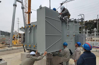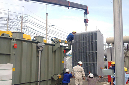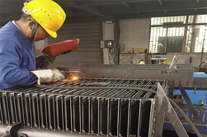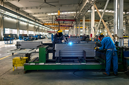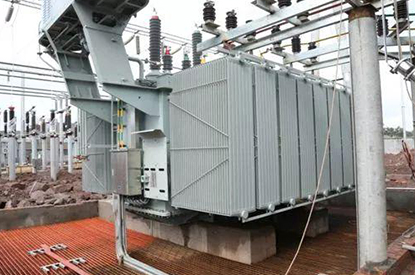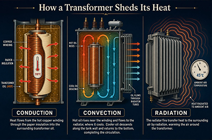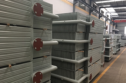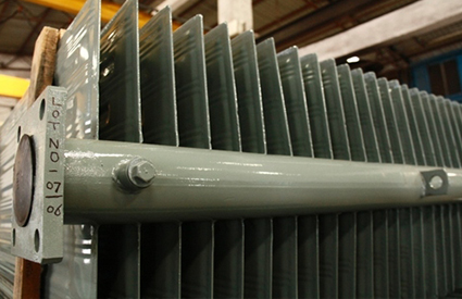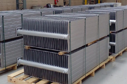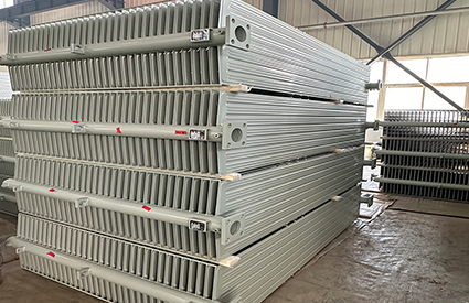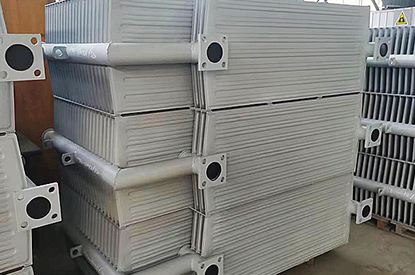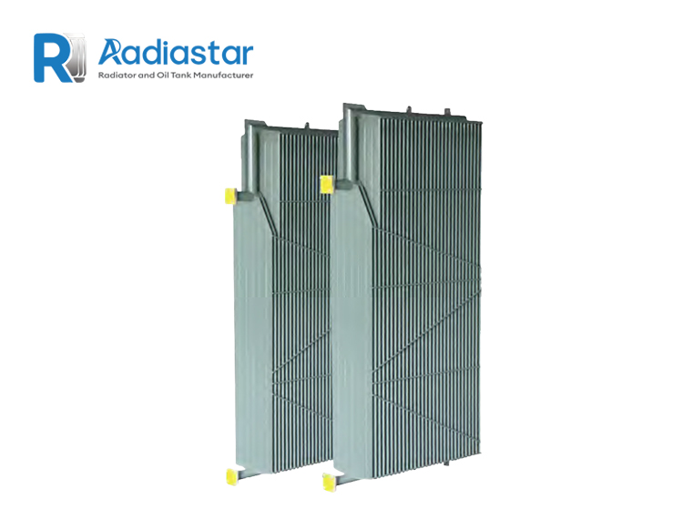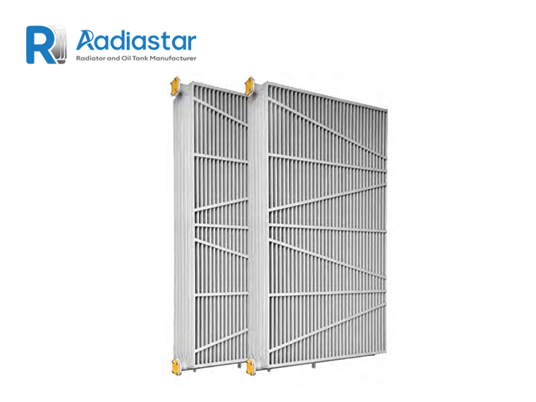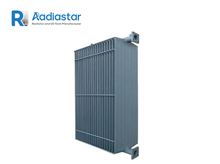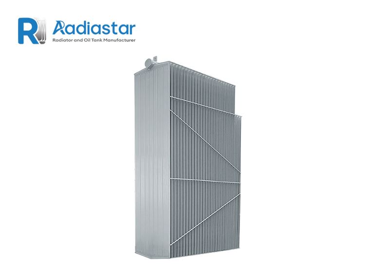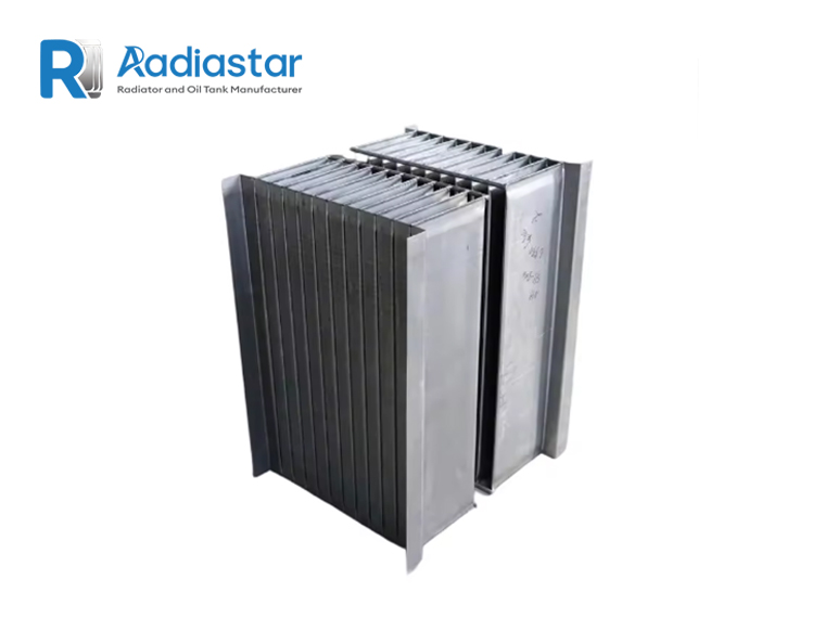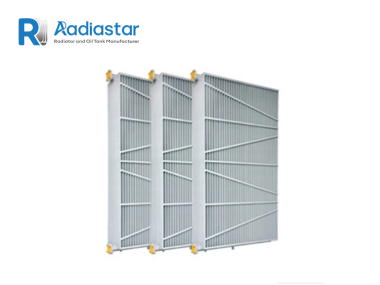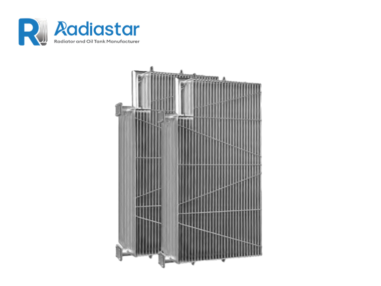

A transformer radiator is one of the primary heat-transfer components in a liquid-immersed transformer cooling system. Its purpose is to transfer heat from the insulating liquid to the surrounding air and maintain the transformer within its specified temperature-rise limits.
However, transformer radiator heat dissipation calculation is often oversimplified. A common approach is to estimate the required radiator surface area from transformer MVA or to multiply the surface area by a fixed heat-dissipation coefficient.
Although such simplified calculations may be useful during preliminary estimation, they are not sufficient for final engineering design.
Actual radiator heat dissipation depends on several interacting factors, including:
For a complete transformer thermal design, the radiator must be considered together with the transformer tank, oil circulation path, cooling equipment and specified temperature-rise limits.
IEC 60076-2 establishes requirements for temperature rise of liquid-immersed transformers and identifies transformer cooling methods and temperature-rise test methods.
IEC 60076-22-2 specifically applies to removable radiators mounted on liquid-immersed power transformers and covers relevant operating conditions, mechanical requirements, preferred dimensions and type and routine testing.
This guide explains the engineering principles behind transformer radiator heat dissipation calculations and shows how engineers can approach preliminary radiator sizing.
During transformer operation, electrical losses are converted into heat.
The main sources are:
Core losses, also called no-load losses, are primarily associated with the magnetic core.
They exist whenever the transformer is energized.
Load losses are mainly associated with current flowing through the windings and other load-dependent effects.
At a simplified level:
Therefore, load losses increase significantly as transformer loading increases.
The total transformer heat generated under a particular operating condition can be approximated as:
where:
For a load factor , if the manufacturer’s load loss is specified at rated current:
Therefore:
This gives the engineer an initial estimate of the heat that must ultimately be removed by the transformer cooling system.
One of the most important points in transformer radiator calculation is:
Radiator capacity should not be determined from transformer MVA alone.
Consider two 20 MVA transformers.
They may have different:
Consequently, their total heat generation may differ.
For example:
| Parameter | Transformer A | Transformer B |
|---|---|---|
| Rated power | 20 MVA | 20 MVA |
| No-load loss | 12 kW | 15 kW |
| Load loss | 90 kW | 105 kW |
| Cooling | ONAN/ONAF | ONAN/ONAF |
Although both transformers have the same MVA rating, their thermal loads are different.
Therefore, a professional radiator calculation should start with actual transformer loss data, not simply the transformer rating.
Suppose a transformer has:
The load factor is:
The approximate load loss is:
Total losses are approximately:
Therefore, under this simplified operating condition, approximately 69.6 kW of heat is generated by the transformer losses.
This does not mean that the radiator must simply be rated at exactly 69.6 kW.
The complete thermal design must consider how the heat is distributed between:
For final design, the transformer manufacturer’s thermal calculation and temperature-rise verification take precedence.
A simplified heat-transfer relationship for a radiator can be expressed as:
where:
This equation is useful for understanding the relationship between radiator surface area and thermal performance.
However, engineers should be careful when applying it to transformer radiators.
The value of U is not a universal constant.
It depends on:
Therefore:
Do not use a generic U-value to produce a final radiator design without validating the operating conditions.
The driving force for heat transfer is the temperature difference between the transformer oil and ambient air.
A simplified relationship is:
Suppose:
Average oil temperature = 80°C
Ambient temperature = 40°C
Then:
If the average oil temperature rises while ambient temperature remains constant, the potential heat-transfer driving force increases.
However, transformer design cannot simply increase oil temperature to increase radiator heat dissipation.
The transformer must remain within its specified temperature-rise and hot-spot limits.
IEC 60076-2 addresses temperature-rise limits for liquid-immersed transformers and provides methods for temperature-rise testing.
Another important issue is the temperature used in the calculation.
Engineers may encounter:
These temperatures are not interchangeable.
For thermal calculations, the effective temperature difference should be based on the relevant thermal model and transformer cooling arrangement.
IEC 60076-2 distinguishes top-liquid, average-liquid and bottom-liquid temperature rise in its temperature-rise framework.
Therefore, using:
Top oil temperature − ambient temperature
as the only temperature difference may over-simplify the actual radiator thermal calculation.
ONAN means:
Oil Natural Air Natural
In an ONAN transformer, both oil circulation and air circulation are primarily natural.
The oil heated inside the transformer rises because of density differences and flows toward the upper radiator connections.
The oil then travels through the radiator.
As heat is transferred to the surrounding air, the oil cools and becomes denser.
The cooler oil returns toward the lower part of the transformer.
The simplified circulation path is:
Transformer active part
↓
Hot oil
↓
Upper radiator connection
↓
Radiator
↓
Heat transfer to ambient air
↓
Cooler oil
↓
Lower radiator connection
↓
Transformer
The effectiveness of this natural circulation depends strongly on the hydraulic and thermal design.
ONAF means:
Oil Natural Air Forced
In ONAF operation, oil circulation remains natural while fans force air through the radiator.
The additional air movement can substantially increase heat transfer.
Therefore, a radiator bank may have two operating capacities:
Heat dissipation under natural air circulation.
Heat dissipation with forced airflow.
For example, a transformer cooling design might specify:
20 MVA ONAN / 25 MVA ONAF
The radiator system must therefore support the required thermal performance at both operating stages.
IEC 60076-2 recognizes alternative cooling methods such as ONAN/ONAF and relates the specified transformer power to the applicable cooling condition.
For preliminary engineering, the simplified heat-transfer equation can be rearranged:
where:
Assume:
Required heat dissipation = 100 kW
Effective temperature difference = 40 K
For preliminary calculation, assume a validated design value of:
U = 10 W/m²·K
Then:
This gives a preliminary effective heat-transfer area of approximately:
250 m²
But this number should not be treated as a universal radiator requirement.
Changing the assumed U-value from 10 to 15 W/m²·K would produce a substantially different result.
This demonstrates why radiator manufacturers should provide validated thermal-performance data rather than relying on generic area calculations.
A transformer radiator is typically composed of multiple cooling elements or fins.
The effective heat-transfer area may include:
Therefore, the geometric surface area and the effective thermal area used in a manufacturer’s performance calculation are not necessarily identical.
When comparing two radiator designs, engineers should therefore ask:
How is the quoted heat-dissipation capacity defined and under what test conditions?
This is much more meaningful than comparing only:
“Radiator surface area = X m².”
Several radiator dimensions directly influence thermal performance.
Increasing radiator height generally increases available heat-transfer area.
However, the practical maximum is constrained by:
A wider radiator can provide additional heat-transfer surface within the same general height.
However, increased width may affect:
Adding fins generally increases heat-transfer area.
But excessive fin density can influence:
Therefore:
More fins do not automatically mean proportionally greater cooling performance.
Transformer radiator performance depends not only on external air cooling but also on the internal oil circulation.
For ONAN systems, oil circulation is driven naturally.
The temperature difference and density difference between hot and cold oil create the circulation force.
The radiator must therefore provide a suitable hydraulic path.
If the oil-flow resistance is too high, the actual oil circulation can be reduced.
This can lower the thermal performance of the radiator bank.
For forced-oil systems, pumps provide the circulation force, but the oil-flow distribution through the cooling circuit still needs to be considered.
This is why thermal calculation and hydraulic calculation should not be treated as completely independent tasks.
Ambient temperature has a direct influence on transformer cooling.
Consider two identical transformer radiator systems:
Ambient temperature:
25°C
Ambient temperature:
45°C
Even if the transformer produces exactly the same losses, the available temperature difference between oil and ambient air will be different.
Higher ambient temperature generally makes heat rejection more difficult.
IEC 60076-2 specifies normal cooling conditions and provides requirements for cases where service conditions differ from those normal conditions.
Therefore, the radiator design should identify the actual site conditions rather than assuming a standard ambient temperature.
Altitude can also affect transformer cooling.
At higher altitude, air density decreases.
This can influence natural convection and forced-air cooling performance.
IEC 60076-2 includes provisions for special service conditions, including altitude effects on air-cooled transformers.
Therefore, when a transformer is installed at high altitude, the radiator and fan system may need to be evaluated accordingly.
The RFQ should specify:
Installation altitude above sea level
rather than simply:
Outdoor installation.
Once the thermal capacity of an individual radiator section or bank is known, the required quantity can be estimated using:
where:
Suppose:
Required heat dissipation = 120 kW
and:
One radiator bank = 20 kW
Then:
Therefore, approximately:
6 radiator banks
would be required before considering the final design margin and mechanical arrangement.
Again, the 20 kW value is an illustrative engineering assumption, not a universal radiator rating.
The actual value must be obtained from the radiator manufacturer’s thermal design data.
A radiator design should not normally be based on a theoretical minimum with zero margin.
Depending on the project specification, the engineer may consider:
However, an arbitrary oversized radiator is not necessarily the best solution.
Excessive radiator capacity can increase:
The objective is:
Adequate thermal performance with an optimized radiator configuration.
The radiator is not necessarily the only component transferring heat to the environment.
The transformer tank itself can also dissipate heat.
The complete thermal balance may therefore include:
For some transformer designs, tank heat dissipation can contribute meaningfully to the overall cooling system.
However, the exact contribution depends on:
Therefore, the radiator should be sized as part of the complete transformer thermal design, not as an isolated component.
Surface treatment is important primarily for corrosion protection and service life, but it can also influence the surface’s thermal and radiative characteristics.
Common radiator protection methods include:
The final coating system should be compatible with:
For coastal or highly corrosive environments, the corrosion-protection specification should be established at the project design stage.
For a professional project, the following workflow is recommended.
Example:
20 MVA
Example:
80%, 100%, overload condition
Confirm:
Establish the required radiator cooling capacity under each operating condition.
Define:
Check oil circulation and pressure drop.
Confirm that the complete transformer remains within specified temperature-rise limits.
Check:
Define:
IEC 60076-22-2 specifically addresses removable radiators and includes requirements concerning preferred dimensions and type and routine testing.
A radiator manufacturer should ideally receive the following information:
| Parameter | Example |
|---|---|
| Transformer rating | 20 MVA |
| Rated voltage | 110/11 kV |
| Cooling mode | ONAN/ONAF |
| No-load loss | 12 kW |
| Load loss | 90 kW |
| Ambient temperature | 40°C |
| Installation altitude | 1000 m |
| Required temperature rise | Project specification |
| Radiator type | Detachable finned |
| Center distance | 1500 mm |
| Fin width | Project specification |
| Fin thickness | Project specification |
| Number of fins | To be calculated |
| Radiator connection | Flange |
| Radiator quantity | To be calculated |
| Surface treatment | Painting / HDG |
| Installation | Outdoor |
If a transformer manufacturer’s thermal calculation is already available, providing that document is even better than asking the radiator supplier to estimate the thermal load from MVA alone.
MVA represents electrical capacity, not heat generation.
Actual transformer losses should be used whenever available.
A fixed coefficient without clearly defined operating conditions can produce misleading results.
A radiator designed for 25°C ambient may not provide the same temperature-rise performance at 45°C ambient.
ONAN and ONAF performance should be evaluated separately when both ratings are specified.
A large radiator surface cannot compensate indefinitely for inadequate oil circulation.
Two radiators with similar dimensions may have different thermal performance because of differences in geometry, oil flow and air-side heat transfer.
A preliminary heat-balance calculation is useful for selecting an initial configuration.
Final transformer thermal performance should be verified through the manufacturer’s thermal design and applicable testing requirements.
When comparing transformer radiator suppliers, the following questions are useful:
What is the rated heat-dissipation capacity of the radiator?
Under what oil temperature, ambient temperature and airflow condition was the capacity determined?
What are the radiator center distance, width, fin thickness and fin number?
What is the pressure drop or hydraulic resistance?
What flange and connection dimensions are available?
What pressure and leakage tests are performed?
Which IEC or project standards are applied?
Can the radiator be manufactured according to an existing transformer tank drawing?
These questions are more useful than comparing supplier quotations only by price.
Consider a hypothetical transformer:
Rated power: 25 MVA
No-load loss: 15 kW
Rated load loss: 110 kW
Cooling: ONAN/ONAF
Ambient temperature: 40°C
At rated load:
Therefore, the transformer produces approximately:
125 kW of total losses
at the assumed rated operating condition.
The next step is not simply to divide 125 kW by an arbitrary radiator coefficient.
The engineer should determine:
Only after these factors are established can the radiator bank be properly selected.
Calculation is essential during design, but actual transformer thermal performance must ultimately be validated according to the applicable project and standard requirements.
IEC 60076-2 specifies temperature-rise testing methods for liquid-immersed transformers.
For removable radiators, IEC 60076-22-2 specifies relevant radiator requirements and type/routine testing provisions.
This is why a professional radiator manufacturer should be able to provide technical documentation covering:
Transformer radiator heat dissipation calculation is fundamentally a thermal-design problem.
The correct approach is:
Transformer rating
↓
Actual transformer losses
↓
Operating load
↓
Required heat rejection
↓
Temperature-rise requirement
↓
ONAN / ONAF cooling mode
↓
Radiator thermal performance
↓
Radiator surface area
↓
Radiator quantity and dimensions
↓
Oil-flow verification
↓
Thermal testing
The key point is that there is no single radiator size or universal W/m² value that applies to every transformer.
A reliable calculation must consider the actual transformer losses, temperature conditions, cooling method, radiator geometry and oil circulation.
For a new transformer project, the most useful information to provide to a radiator manufacturer is:
MVA + voltage + no-load loss + load loss + cooling method + temperature rise + ambient temperature + radiator connection dimensions.
With these parameters, the radiator supplier can develop a technically appropriate configuration rather than relying on a simple MVA-based estimate.