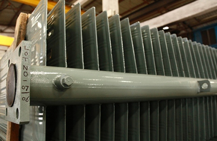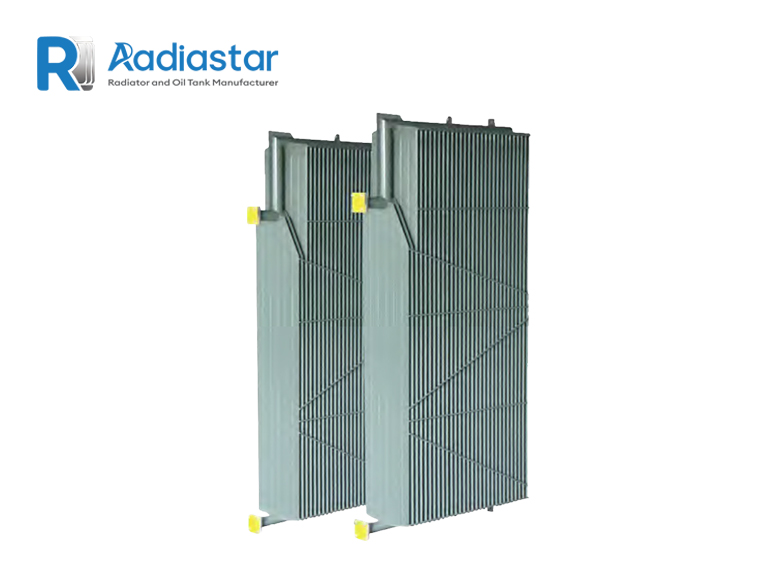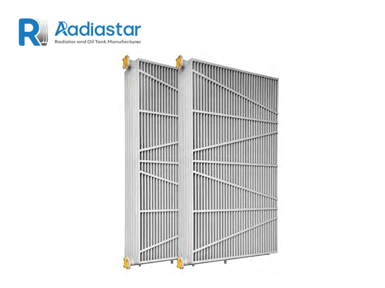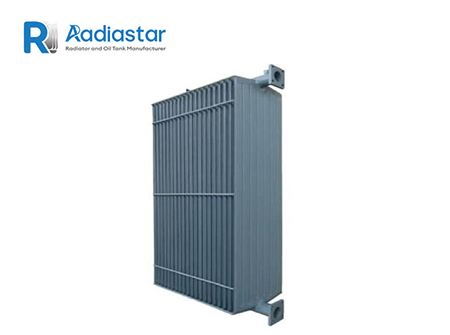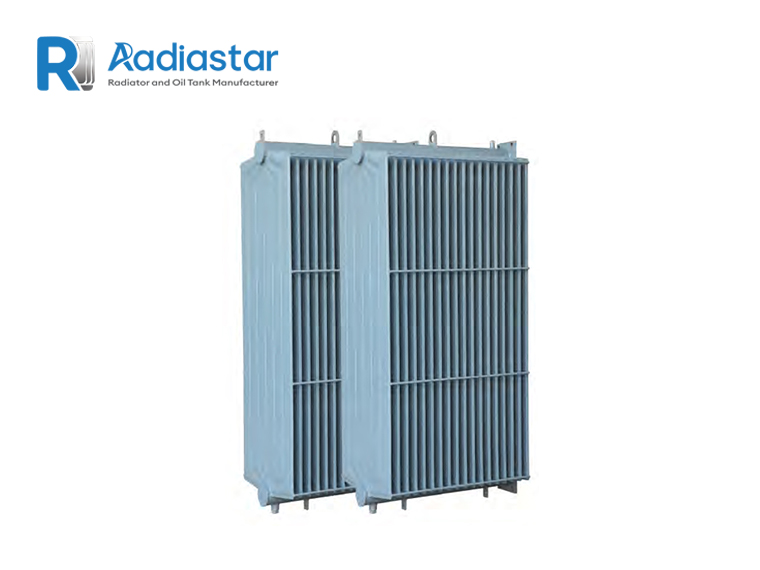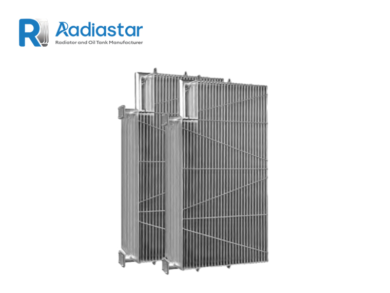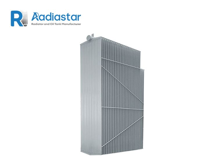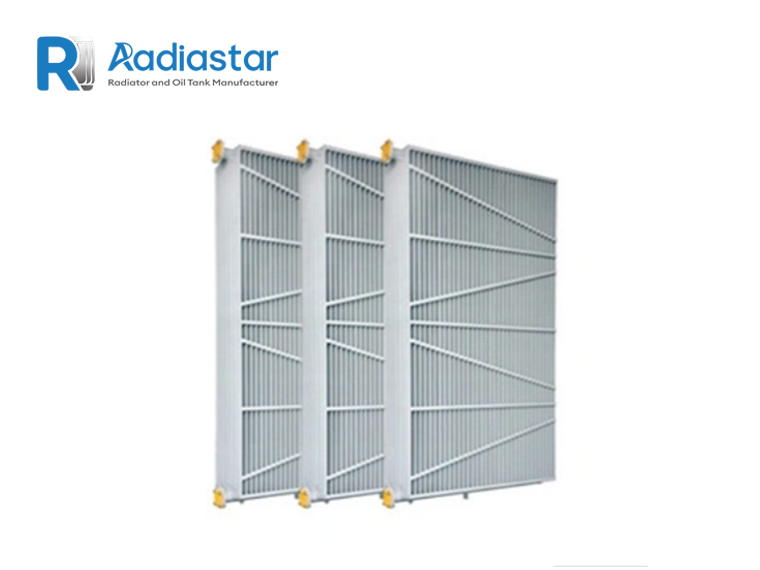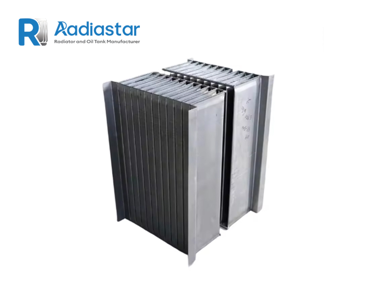

Choosing the correct transformer radiator size is an important part of designing the cooling system for an oil-immersed transformer.
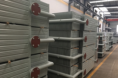
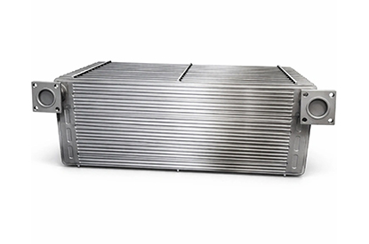
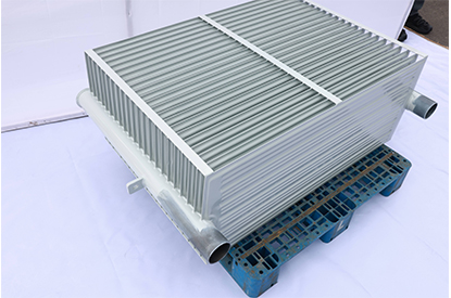
Radiator dimensions affect much more than the physical appearance of the transformer. The radiator’s center distance, fin width, height, number of fins, fin pitch, panel arrangement and connection dimensions influence heat-transfer area, oil circulation, installation space, weight, transportation and compatibility with the transformer tank.
For this reason, a transformer radiator should not be selected simply by saying:
“The transformer is 20 MVA, so we need a 2-meter radiator.”
The transformer MVA rating is only one input. The correct radiator dimensions depend on the required thermal capacity and the mechanical arrangement of the transformer.
IEC 60076-22-2 specifically covers removable radiators mounted on liquid-immersed power transformers and includes requirements concerning service conditions, mechanical requirements, preferred dimensions and type and routine testing.
In practical engineering, radiator sizing normally follows this sequence:
Transformer thermal requirement → radiator type → center distance → fin width → number of fins → radiator quantity → connection dimensions → mechanical verification
This guide explains how each dimension should be understood and how engineers can select a suitable transformer radiator configuration.
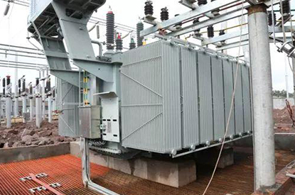
A transformer radiator is a heat-transfer device used with oil-immersed transformers.
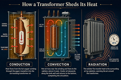
During operation, transformer losses generate heat inside the active part. The insulating oil absorbs this heat and circulates through the transformer cooling system.
In a typical natural-cooling arrangement:
Hot oil → upper radiator connection → radiator → heat transfer → cooled oil → lower radiator connection → transformer
The radiator provides a large external surface area through which heat can be transferred from the transformer oil to ambient air.
For larger transformers, radiators may operate with:
The same basic radiator geometry can sometimes be used for different cooling stages, but the available thermal capacity changes with airflow and oil circulation.
Therefore, dimensions must always be considered together with the cooling mode.
A radiator’s dimensions affect four major engineering areas:
Larger effective surface area generally provides greater heat-transfer capability.
The radiator geometry influences oil-flow resistance and natural circulation.
The radiator must fit the transformer tank connection points and available installation space.
Large radiators increase:
Therefore, the objective is not to select the biggest possible radiator.
The objective is:
Select the smallest practical configuration that meets the required thermal and mechanical performance.
When discussing transformer radiator dimensions, engineers normally consider:
These parameters are related, but they are not interchangeable.
For example, increasing center distance increases radiator height, while increasing the number of fins increases the effective width of the radiator assembly.
Center distance, often abbreviated as CC, is one of the most important dimensions when specifying a transformer radiator.
It normally refers to the distance between the centers of the upper and lower oil connection points.
A simplified representation is:
The center distance determines how the radiator fits vertically between the upper and lower connection points on the transformer tank.
It is therefore both a thermal parameter and a mechanical interface parameter.
Transformer radiator manufacturers commonly produce a range of center distances.
Depending on the manufacturer and project specification, typical values may include:
The exact available range depends on the radiator design.
For example, some manufacturers offer center distances from approximately 500 mm to 4000 mm, with larger dimensions available as customized products.
Radiastar’s current radiator product range covers customized center distances, with product specifications extending from approximately 300 mm to 3500 mm on its oil-immersed transformer radiator range.
The important point is:
Center distance should be specified according to the transformer tank drawing, not selected only according to transformer MVA.
For a replacement radiator, the safest method is to use the existing radiator or transformer tank drawing.
Measure:
Center of upper oil connection → center of lower oil connection
Do not measure:
and assume that this is the center distance.
These dimensions can be different.
For a new transformer project, the transformer manufacturer should provide the required radiator connection layout.
The radiator supplier can then design the radiator around the specified interface.
Increasing center distance generally provides a larger vertical heat-transfer area.
For the same radiator width and fin configuration:
Longer center distance → larger radiator surface → potentially greater heat dissipation
However, the relationship is not simply:
Double the center distance = double the cooling capacity.
Actual heat dissipation depends on:
Therefore, the center distance should be evaluated together with the radiator’s validated thermal performance.
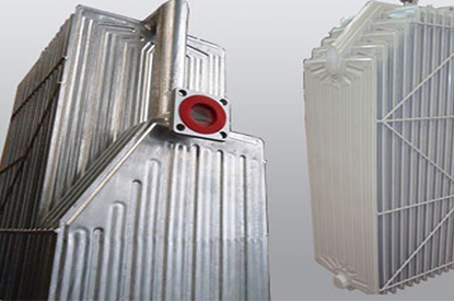
Fin width is the width of the cooling panel or fin assembly.
Common transformer radiator configurations may use widths such as:
Current commercial radiator ranges show examples of 310 mm, 480 mm, 520 mm and 535 mm panel widths.
Radiastar’s product specifications also include customized fin widths depending on radiator design.
Fin width affects the available heat-transfer area.
A wider fin can provide more cooling surface without necessarily increasing radiator height.
The choice between different widths should not be made simply according to which one has the largest surface.
A simplified comparison is:
| Parameter | Narrower Fin | Wider Fin |
|---|---|---|
| Heat-transfer area | Lower | Higher |
| Radiator footprint | Smaller | Larger |
| Weight | Lower | Higher |
| Airflow requirement | Different | Different |
| Transportation | Easier | More demanding |
| Installation space | Smaller | Larger |
| Typical application | Compact systems | Higher cooling requirements |
A narrower radiator may be appropriate when installation space is limited.
A wider radiator may be preferred when higher heat-transfer area is required within a limited vertical dimension.
The final choice depends on the transformer thermal design.
The number of fins refers to the number of individual cooling elements forming a radiator panel or section.
Increasing the number of fins generally increases the available heat-transfer surface.
For example, a radiator may contain:
10 fins
15 fins
20 fins
25 fins
or more depending on its dimensions.
Radiastar’s stainless-steel transformer radiator specifications, for example, list configurations with 1–45 fins, with fin pitch options including 40, 45 and 50 mm depending on design.
The exact number is normally selected together with:
Fin pitch is the distance between adjacent cooling fins.
A typical radiator may use different fin pitches depending on:
For example, Radiastar lists 40 mm, 45 mm and 50 mm fin-pitch configurations for one stainless-steel radiator range.
A smaller pitch allows more fins within a given width, but increasing fin density does not automatically produce proportional improvements in cooling performance.
If fins are packed too closely, airflow conditions can change.
Therefore:
Fin number and fin pitch should be optimized together rather than maximizing fin density.
A simplified concept is:
where:
This is only a geometric relationship.
Actual thermal performance also depends on:
Therefore, geometric surface area should not be directly interpreted as guaranteed heat-dissipation capacity.
Radiator height is closely related to center distance.
For a practical installation, the overall radiator height is greater than the center distance because the design also includes:
Therefore:
Center distance ≠ overall radiator height.
This distinction is particularly important when checking the available installation space around a transformer.
For example, a transformer may have:
Center distance = 2000 mm
but the total radiator assembly may be higher than 2000 mm.
When preparing an installation drawing, engineers should therefore request the overall dimensions, not only the center distance.
The overall horizontal length of a radiator bank depends mainly on the number of radiator sections.
A simplified relationship is:
where:
This means that increasing the number of sections can increase cooling capacity but also increases the physical footprint.
For a large transformer, several radiator banks may therefore be distributed around the tank rather than concentrated in one large assembly.
These two parameters are sometimes confused.
Refers to the cooling elements within an individual radiator assembly.
Refers to how many radiator units are arranged together to form a radiator bank.
For example:
20 fins per radiator × 8 radiator sections
is a different specification from:
40 fins per radiator × 4 radiator sections
Even if their theoretical surface areas are similar, their:
may be completely different.
Transformer MVA is useful as an initial reference but should not directly determine radiator dimensions.
A better engineering sequence is:
Transformer MVA
↓
Transformer losses
↓
Required heat dissipation
↓
Cooling method
↓
Required effective cooling area
↓
Radiator center distance
↓
Fin width and fin configuration
↓
Number of sections
↓
Final radiator arrangement
This is why two transformers with identical MVA ratings may use different radiator dimensions.
Consider a hypothetical transformer:
Rated power: 25 MVA
Cooling: ONAN/ONAF
Ambient temperature: 40°C
Required radiator center distance: 2000 mm
The engineer may initially consider:
Center distance: 2000 mm
Fin width: 520 mm
Fin pitch: 45–50 mm
The number of fins can then be determined according to the selected radiator construction and required cooling area.
If additional cooling capacity is required, the designer may consider:
The correct option depends on the transformer tank layout and thermal calculation.
Suppose a transformer requires additional cooling capacity.
There are two common approaches:
For example:
1500 mm → 2000 mm center distance
Advantages:
Disadvantages:
Advantages:
Disadvantages:
The optimum choice depends on the transformer design.
A radiator can have excellent thermal performance and still be unsuitable if its connection does not match the transformer tank.
Important connection parameters include:
Some radiator designs use standard flange interfaces, while others are customized according to the transformer manufacturer’s drawing.
Radiastar’s gooseneck/swan-neck radiator range, for example, supports flange configurations based on ANSI/ASME B16.5 as specified for that product range.
Therefore, a radiator RFQ should always include the tank-side connection drawing whenever possible.
The upper and lower headers provide the oil connection between the transformer and radiator.
Header dimensions affect:
Commercial radiator designs commonly use different header diameters depending on the radiator configuration. For example, one radiator range specifies an approximately 88.9 mm header pipe.
However, header diameter should not be copied from another radiator design.
It should be selected according to:
Radiator fin thickness affects:
Commercial transformer radiator designs commonly use approximately 1.0–1.5 mm steel sheets, while some customized designs use thicker materials depending on operating requirements.
For example, Radiastar lists 1.2 / 1.5 / 2.0 / 2.5 mm radiator material thickness options for its oil-immersed transformer radiator range.
The final thickness should be determined by:
Radiator dimensions also determine the amount of transformer oil contained inside the radiator.
This matters because oil volume affects:
Larger radiator sections contain more oil.
Therefore, when comparing two radiator designs, engineers should evaluate not only:
Cooling area
but also:
Oil capacity + weight + dimensions + thermal performance.
Radiator manufacturers may provide oil capacity per section as part of their technical data. Radiastar’s radiator tables, for example, include oil-weight and cooling-area data for different center distances and fin configurations.
Radiator weight becomes increasingly important for large transformers.
The total radiator weight depends on:
A radiator should therefore be evaluated from both an engineering and logistics perspective.
For export projects, the supplier should consider:
For large transformer projects, these considerations can affect the total project cost significantly.
Replacement radiators require a different approach from new transformer design.
For a replacement project, the priority is usually:
If the original radiator is still available, the supplier should obtain:
If the original manufacturer is known, the original radiator drawing is even better.
For a new transformer, radiator sizing should start from the transformer thermal specification.
The purchaser should provide:
| Parameter | Required Information |
|---|---|
| Transformer rating | MVA |
| Voltage | kV |
| Cooling | ONAN / ONAF / OFAF |
| No-load loss | kW |
| Load loss | kW |
| Temperature rise | °C |
| Ambient | °C |
| Altitude | m |
| Radiator center distance | mm |
| Connection | Flange / welded |
| Radiator quantity | Required / to calculate |
| Material | Carbon steel / stainless steel |
| Coating | Paint / galvanized |
| Installation | Indoor / outdoor |
With these parameters, the radiator manufacturer can optimize the dimensions.
A professional radiator datasheet should allow the engineer to determine at least:
A supplier that provides only:
“High efficiency transformer radiator”
without dimensions and technical data is difficult for an engineering department to evaluate.
The following is a practical reference rather than a universal standard table:
| Parameter | Typical / Available Range |
|---|---|
| Center distance | 500–4000+ mm |
| Fin width | 300–535+ mm |
| Fin thickness | 1.0–2.5 mm |
| Fin pitch | 40–50 mm examples |
| Number of fins | Application dependent |
| Header diameter | Application dependent |
| Connection | Flange / welded |
| Cooling | ONAN / ONAF / OFAF |
| Material | Carbon steel / stainless steel |
| Surface treatment | Painting / galvanizing / customized |
Commercial radiator manufacturers publish different ranges, so the figures above should be treated as reference ranges, not mandatory IEC dimensions. IEC 60076-22-2 addresses preferred dimensions for removable radiators, but project requirements and manufacturer designs determine the actual configuration.
When requesting a transformer radiator quotation, the following five dimensions should never be omitted:
CC = ____ mm
W = ____ mm
N = ____
Upper / Lower flange = ____
L × W × H = ____
These five parameters allow the supplier to determine whether a standard radiator configuration can be used or whether an OEM design is required.
For custom transformer radiator projects, Radiastar’s current product specifications cover configurations for oil-immersed distribution and power transformers, with options for ONAN, ONAF and OFAF cooling arrangements. Its published range includes customized center distances, radiator heights, panel quantities, connection types and corrosion-protection systems.
For example, the current product range includes:
The actual dimensions should be finalized according to the transformer thermal calculation and tank interface rather than selected only from a generic catalog.
Before approving the radiator drawing, engineers should check:
The correct transformer radiator size cannot be determined from transformer MVA alone.
A professional radiator selection should consider:
Transformer losses
→ Required heat dissipation
→ Cooling method
→ Center distance
→ Fin width
→ Fin pitch
→ Number of fins
→ Radiator sections
→ Connection dimensions
→ Oil circulation
→ Installation and transportation
Among these parameters, center distance and connection dimensions are especially important for mechanical compatibility, while fin width, fin number and radiator quantity strongly influence the available cooling surface.
For new transformer projects, the radiator should be designed together with the transformer thermal system. For replacement projects, the existing radiator dimensions and transformer tank connections should be carefully measured before quotation.
IEC 60076-22-2 provides an important international reference for removable radiators used with liquid-immersed power transformers, including preferred dimensions and testing requirements.
For an accurate transformer radiator quotation, provide the transformer MVA, cooling method, radiator center distance, fin width, number of fins, connection dimensions and transformer tank drawing.
Radiastar can develop a customized radiator configuration according to the required thermal performance and transformer mechanical interface.